Control the Mesh
This chapter uses Kiali wizards to configure Istio traffic management on the Travel Demo. Each section introduces a scenario, walks through the wizard, verifies the result in Kiali, and ends with guidance to update or delete the generated configuration.
In Observe the Mesh you explored telemetry and tracing. Here you change how traffic flows through the mesh.
Request Routing
The Travel Demo application has several portals deployed on the travel-portal namespace consuming the travels service deployed on the travel-agency namespace.
The travels service is backed by a single workload called travels-v1 that receives requests from all portal workloads.
At some point in the lifecycle the business needs of the portals may differ and new versions of the travels service may be necessary.
This step will show how to route requests dynamically to multiple versions of the travels service.
Step 1
Deploy travels-v2 and travels-v3 workloadsDeploy the new versions of the travels service:
kubectl apply -f <(curl -L https://raw.githubusercontent.com/kiali/demos/master/travels/travels-v2.yaml) -n travel-agency
kubectl apply -f <(curl -L https://raw.githubusercontent.com/kiali/demos/master/travels/travels-v3.yaml) -n travel-agency
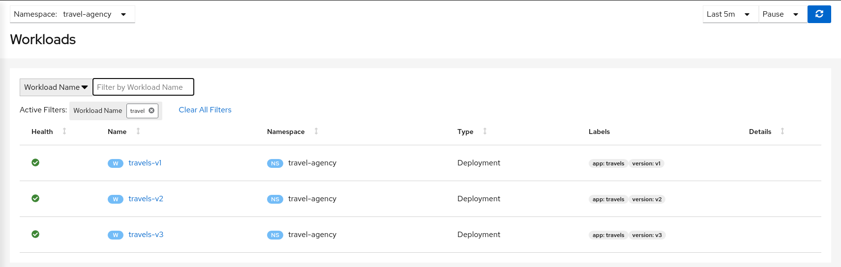
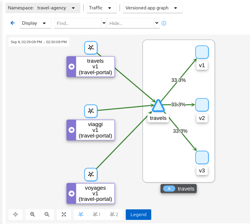
As there is no specific routing defined, when there are multiple workloads for the travels service the request distribution is fairly uniform.
Step 2
Investigate the HTTP headers used by the Travel Demo applicationThe Traffic Management features of Istio allow you to define matching conditions for dynamic request routing.
In our scenario we would like to perform the following routing logic:
- All traffic from travels.uk routed to travels-v1
- All traffic from viaggi.it routed to travels-v2
- All traffic from voyages.fr routed to travels-v3
Portal workloads use HTTP/1.1 to call the travels service, so one strategy is to match on HTTP headers.
Where do those headers come from? That information belongs to the application domain — examine the code, documentation, or a live trace to see which headers are in use.
The Travel Demo uses an Istio annotation on the Deployment pod template to configure the proxy:
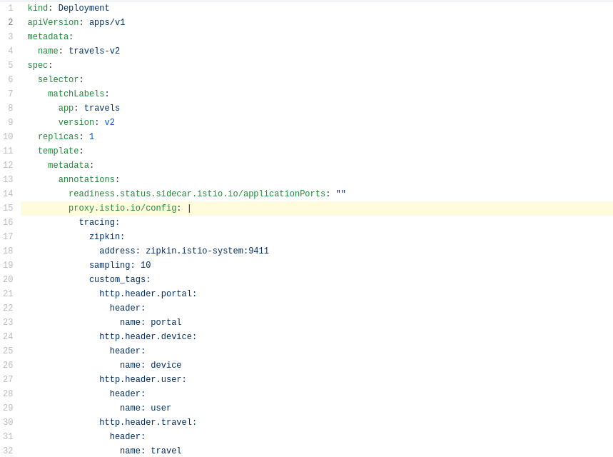
In our example the HTTP headers are added as part of the trace context. Tracing populates custom tags with the portal, device, user, and travel values.
Step 3
Use the Request Routing wizard on the travels service- Open Services.
- Select the travel-agency namespace.
- Click the travels service.
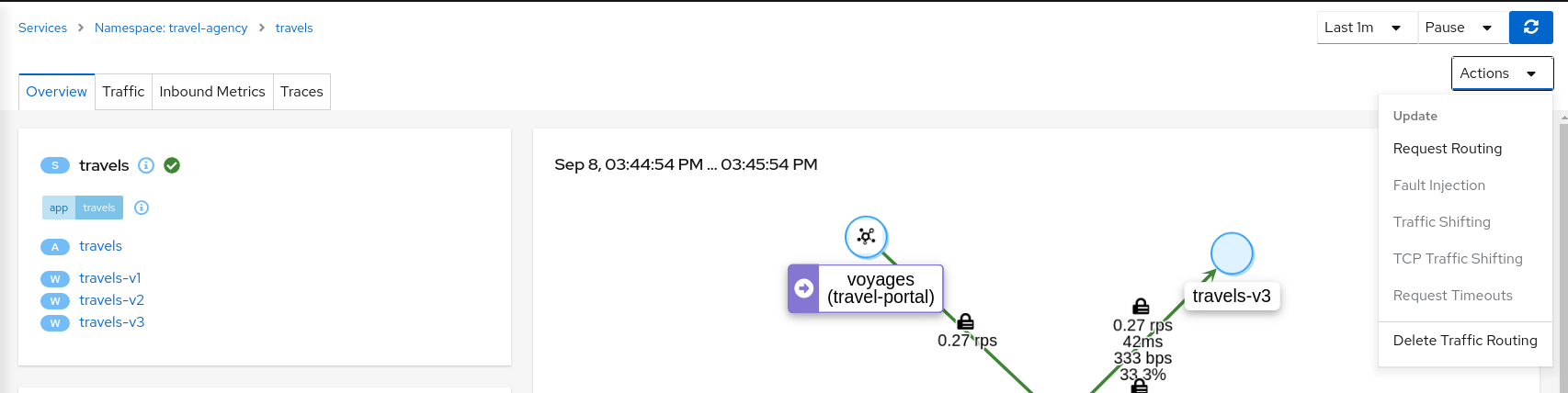
- Select Actions → Request Routing.
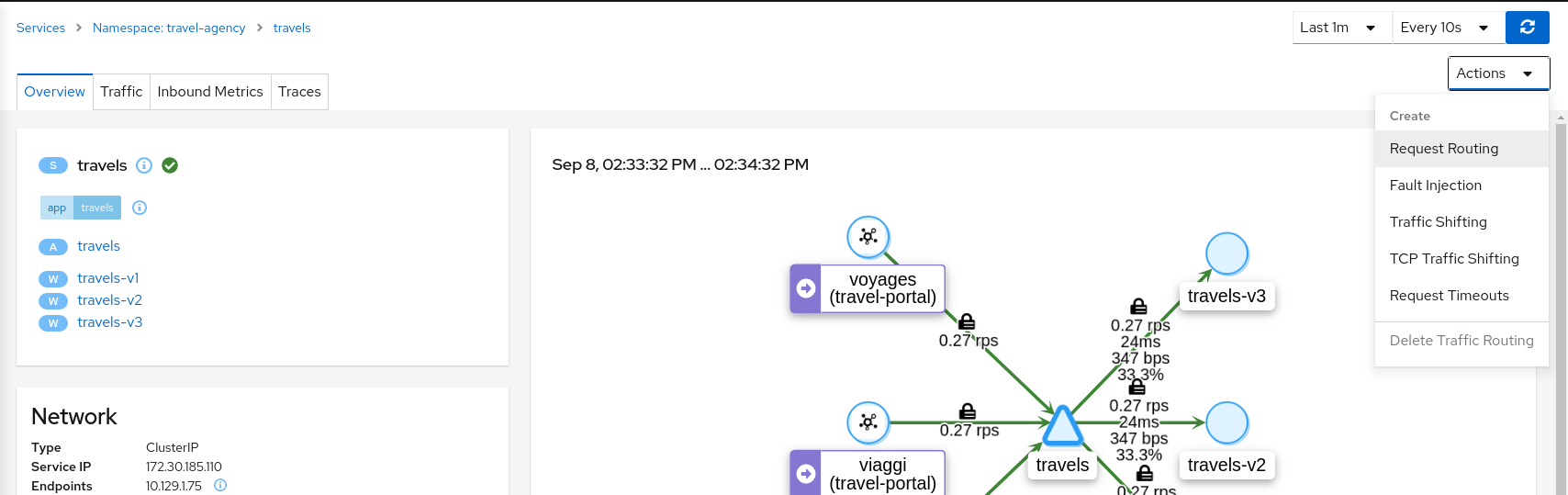
Define three request-matching rules before clicking Create.
For the first rule, match when the portal header equals travels.uk:
- Open the Request Matching tab.
- Add an exact match for the portal header with value travels.uk.
- Click Add Match to update Matching selected for this rule.

- Open the Route To tab and set the destination workload for this rule.
- Click Add Route Rule to save the first rule.
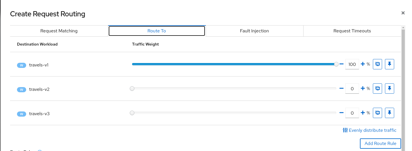
Return to the Request Matching tab and repeat the process, adding rules to route traffic from viaggi.it to travels-v2 and from voyages.fr to travels-v3.
When all three rules are defined, it should look like this:
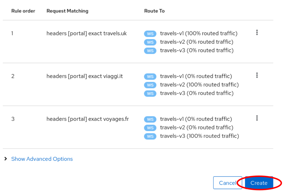
Click Create to generate the Istio configuration. Review the generated config, then confirm to apply it.
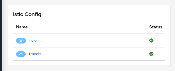
The generated Istio config appears on the Istio Config card on the service detail page.
Step 4
Verify request routing from the travel-portal graphOnce routing is in place, verify that each portal sends traffic to its assigned travels workload:
- Open Traffic Graph.
- Select only the travel-portal namespace.
- Set Graph Type to Workload graph.
- Open Display → under Show Edge Labels, enable Traffic Distribution.
- Open Display → disable Service Nodes.
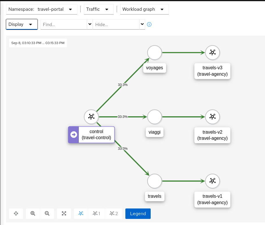
An edge without a distribution label implies 100% of traffic on that path.
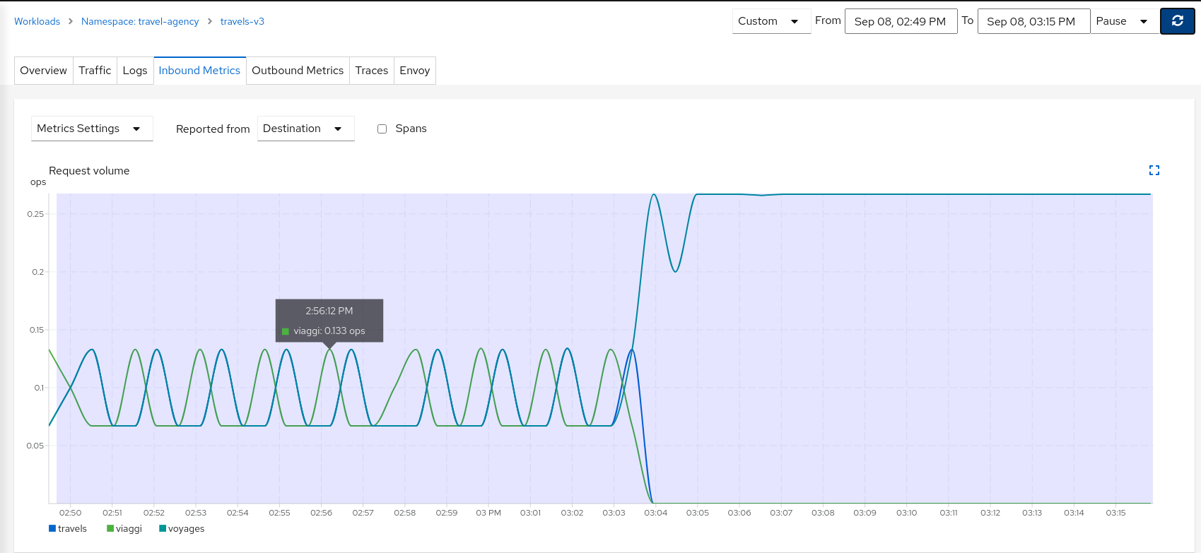
Navigate to any travels workload, open the Inbound Metrics tab, and expand the Request Volume chart for a similar view in the telemetry.
Increase the Duration to Last 30m (or use a custom time range) to show the time when our new routing was defined. We can see how the workload initially received traffic from all portals, then only from a single portal after request routing was applied.
Step 5
Update or delete Istio ConfigurationKiali wizards define high-level mesh scenarios and generate the Istio configuration needed to implement them (VirtualServices, DestinationRules, and related objects). Update or delete a scenario from the Actions menu on the service.
To experiment further, open the travels service and select Actions → Request Routing. When finished, use Actions to delete the generated Istio config.
Fault Injection
The Observe the Mesh chapter identified that the hotels service has additional traffic compared with other services deployed in the travel-agency namespace.
Also, this service is critical in the main business logic. It is responsible for querying all available destinations, presenting them to the user, and getting a quote for the selected destination.
This also means that the hotels service may be one of the weakest points of the Travel Demo application.
This step will show how to test the resilience of the Travel Demo application by injecting faults into the hotels service and then observing how the application reacts to this scenario.
Step 1
Use the Fault Injection wizard on the hotels service to inject a delay- Open Services.
- Select the travel-agency namespace.
- Click the hotels service.
- Select Actions → Fault Injection.
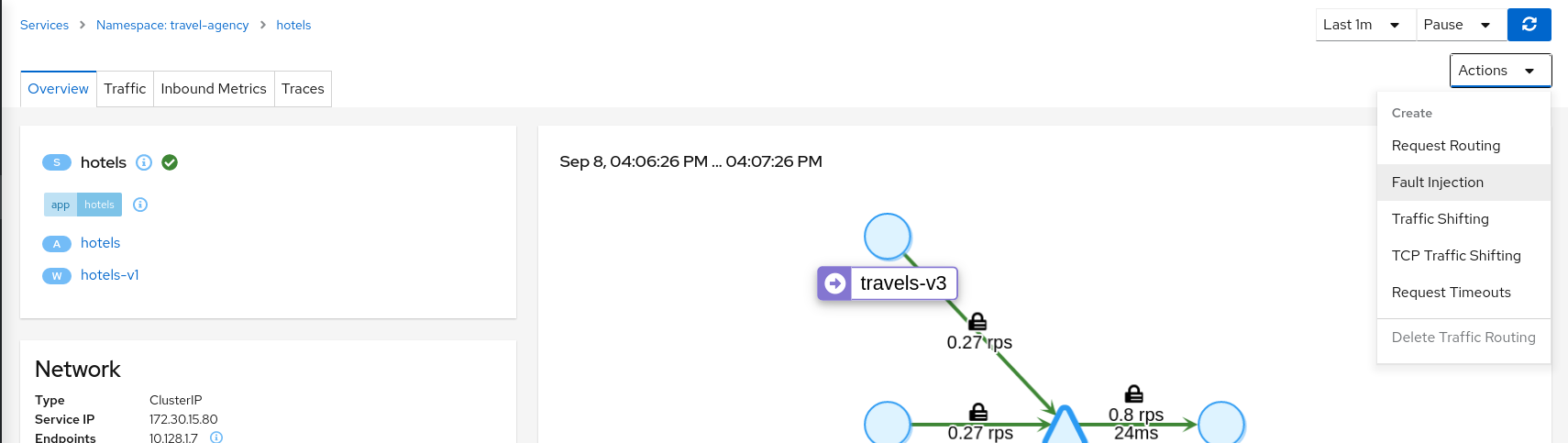
Select HTTP Delay and set Delay percentage and Fixed Delay to the defaults, which introduce a 5 second delay on 100% of requests.
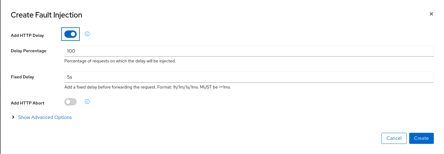
Create the HTTP Delay.
Step 2
Understanding source and destination metricsTelemetry is collected from proxies and it is labeled with information about the source and destination workloads.
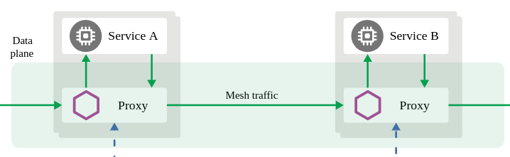
In our example, let’s say that the travels service (“Service A” in the Istio diagram below) invokes the hotels service (“Service B” in the diagram). The travels workload is the “source” and hotels is the “destination” workload. The travels proxy will report telemetry from the source perspective and hotels proxy will report telemetry from the destination perspective. Let’s look at the latency reporting from both perspectives.
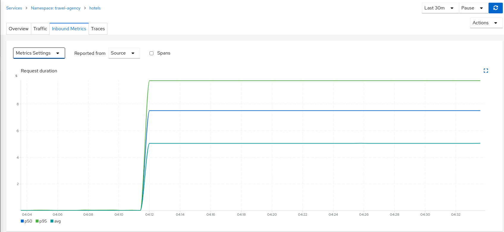
The travels workload proxy has the Fault Injection configuration so it will perform the call to the hotels service and will apply the delay on the travels workload side (this is reported as source telemetry).
We can see in the hotels telemetry reported by the source (the travels proxy) that there is a visible gap showing 5 second delay in the request duration.
Note
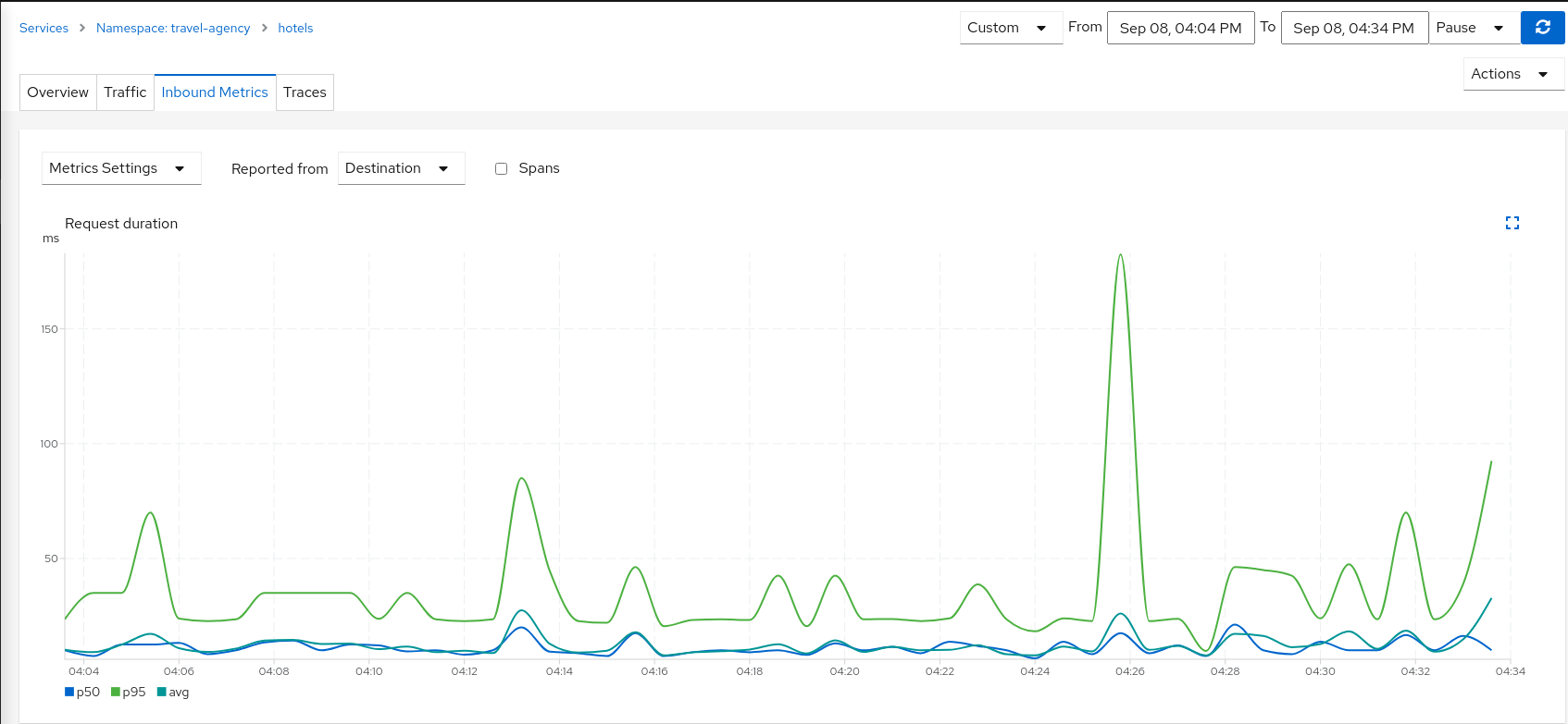
The avg line reflects the injected delay most accurately. p50 and p95 are estimated from Istio’s Prometheus histogram buckets, not from individual request timings. When latency clusters near a bucket boundary (as it does with a fixed delay), quantiles can read lower than the configured delay — for example, with a 5s delay you may see avg just above 5s while p50 reads closer to 3.7s. The same pattern appears at other delay values (try updating the scenario to 4s to compare).But as the Fault Injection delay is applied on the source proxy (travels), the destination proxy (hotels) is unaffected and its destination telemetry shows no delay.
Step 3
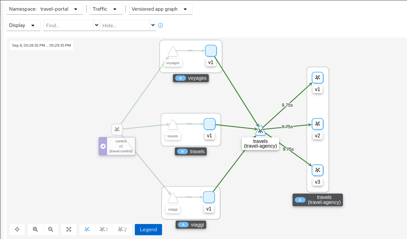
Study the impact of the travels service delayThe injected delay is propagated from the travels service to the downstream services deployed on travel-portal namespace, degrading the overall response time. But the downstream services are unaware, operate normally, and show a green status.
Step 4
Update or delete Istio ConfigurationAs part of this step you can update the Fault Injection scenario to test different delays. When finished, you can delete the generated Istio config for the hotels service.
Traffic Shifting
In the previous Request Routing step we deployed two new versions of the travels service using the travels-v2 and travels-v3 workloads.
That scenario showed how Istio can route specific requests to specific workloads. It was configured such that each portal deployed in the travel-portal namespace (travels.uk, viaggi.it and voyages.fr) was routed to a specific travels workload (travels-v1, travels-v2 and travels-v3).
This Traffic Shifting step will simulate a new scenario: the new travels-v2 and travels-v3 workloads will represent new improvements for the travels service that will be used by all requests.
These new improvements implemented in travels-v2 and travels-v3 represent two alternative ways to address a specific problem. Our goal is to test them before deciding which one to use as a next version.
At the beginning we will send 80% of the traffic into the original travels-v1 workload, and split 10% of the traffic each to travels-v2 and travels-v3.
Step 1
Use the Traffic Shifting wizard on the travels service- Open Services → travel-agency → travels.
- Select Actions → Traffic Shifting.
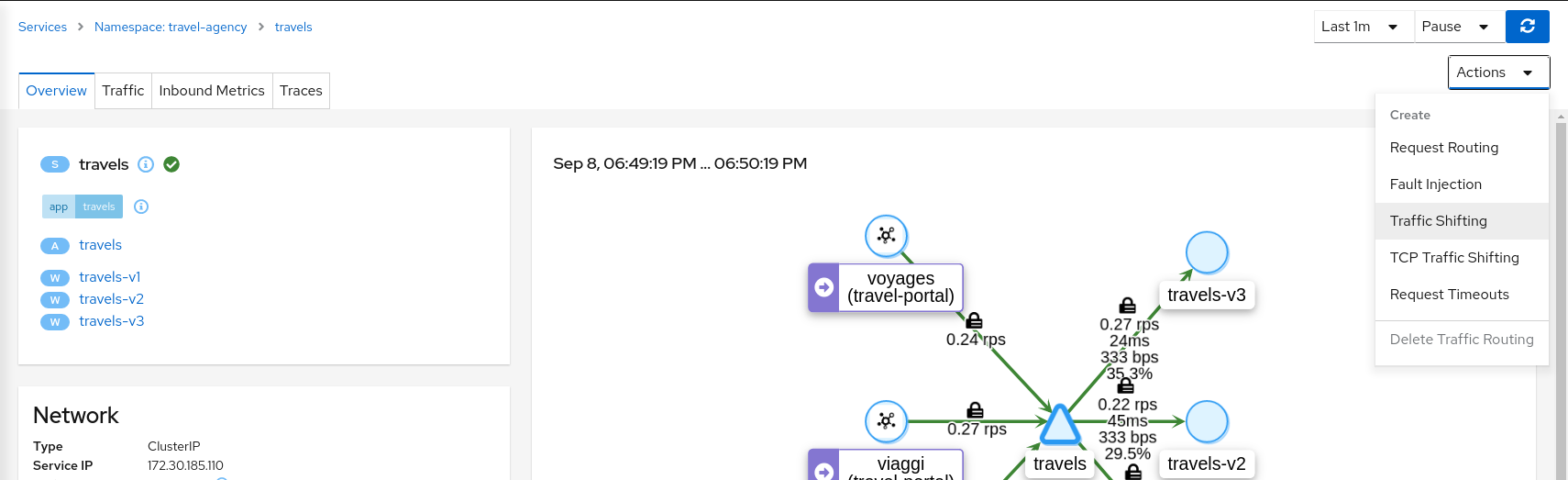
Create a scenario with 80% of traffic to travels-v1 and 10% each to travels-v2 and travels-v3.
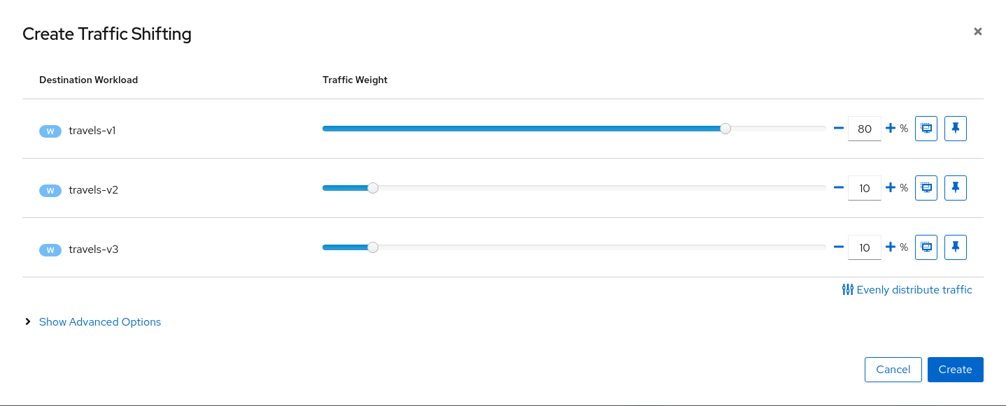
Step 2
Examine Traffic Shifting distribution from the travel-agency travels service Node Graph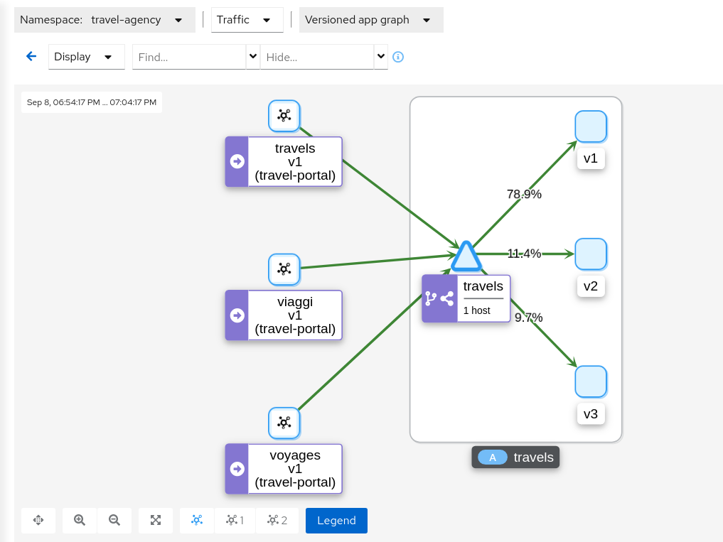
Step 3
Compare travels workload and assess new changes proposed in travels-v2 and travels-v3Istio Telemetry is grouped per logical application. That has the advantage of easily comparing different but related workloads, for one or more services.
In our example, we can use the “Inbound Metrics” and “Outbound Metrics” tabs in the travels application details, group by “Local version” and compare how travels-v2 and travels-v3 are working.
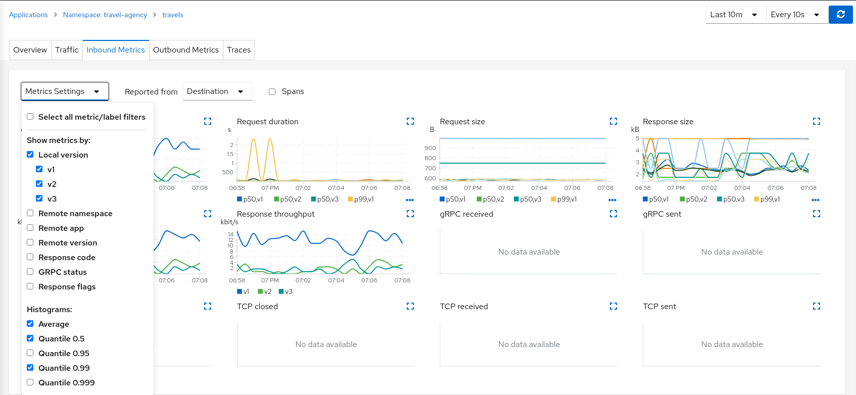
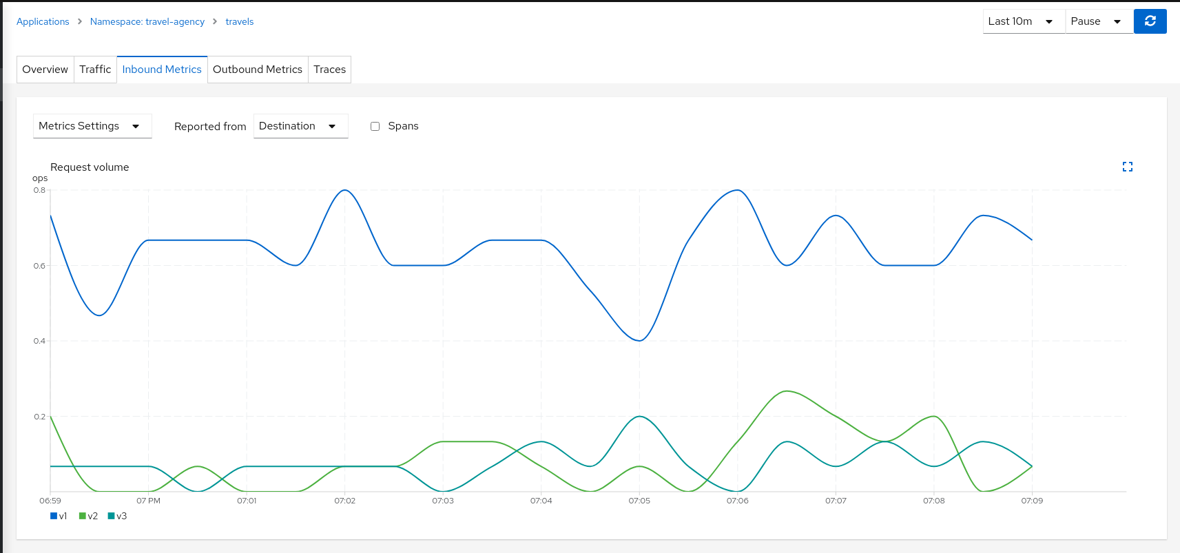
The charts show that the traffic distribution is working as expected and 80% is being distributed to the travels-v1 workload. They also show no big differences between travels-v2 and travels-v3 in terms of request duration.
Step 4
Update or delete Istio ConfigurationAs part of this step you can update the Traffic Shifting scenario to test different distributions. When finished, you can delete the generated Istio config for the travels service.
TCP Traffic Shifting
The Travel Demo application has a database service used by several services deployed in the travel-agency namespace.
At some point in the lifecycle of the application the telemetry shows that the database service degrades and starts to increase the average response time.
This is a common situation. In this case, a database specialist suggests an update of the original indexes due to data growth.
Our database specialist is suggesting two approaches and proposes to prepare two versions of the database service to test which may work better.
This step will show how the “Traffic Shifting” strategy can be applied to TCP services to test which new database indexing strategy works better.
Step 1
Deploy mysqldb-v2 and mysqldb-v3 workloadsTo deploy the new versions of the mysqldb service execute the commands:
kubectl apply -f <(curl -L https://raw.githubusercontent.com/kiali/demos/master/travels/mysql-v2.yaml) -n travel-agency
kubectl apply -f <(curl -L https://raw.githubusercontent.com/kiali/demos/master/travels/mysql-v3.yaml) -n travel-agency
Step 2
Use the TCP Traffic Shifting Wizard on mysqldb service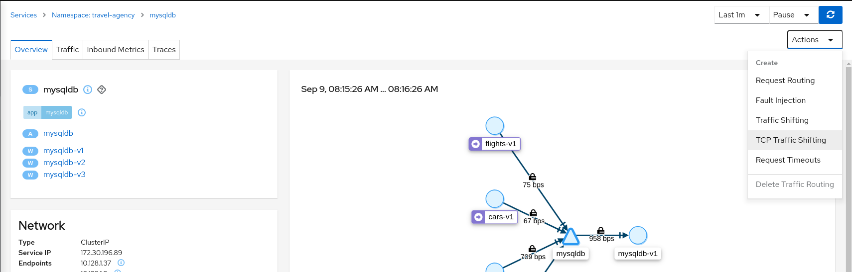
Create a scenario with 80% of the traffic distributed to mysqldb-v1 workload and 10% of the traffic distributed each to mysqldb-v2 and mysqldb-v3.
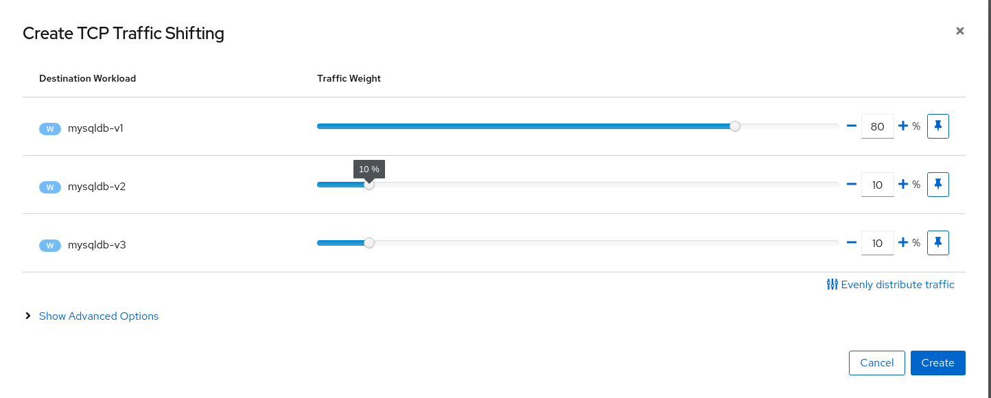
Step 3
Examine Traffic Shifting distribution from the travel-agency Graph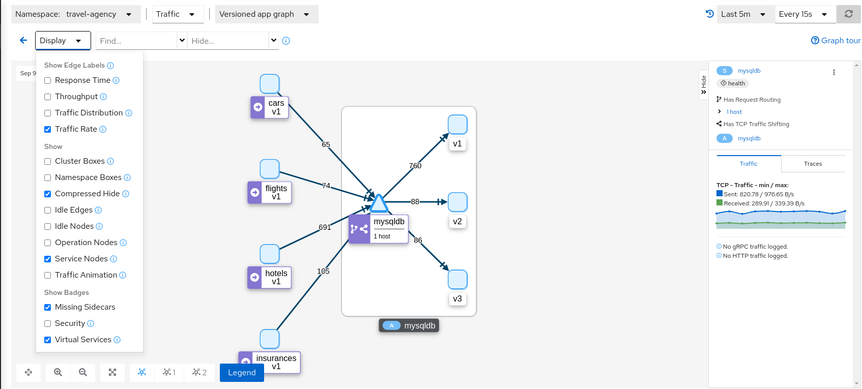
Note that TCP telemetry has different types of metrics. As “Traffic Distribution” is only available for HTTP/gRPC services, for this service we need to use “Traffic Rate” to evaluate the distribution of data (bytes-per-second) between mysqldb workloads.
Step 4
Compare mysqldb workloads and study new indexes proposed in mysqldb-v2 and mysqldb-v3TCP services have different telemetry but it’s still grouped by versions, allowing the user to compare and study pattern differences for mysqldb-v2 and mysqldb-v3.
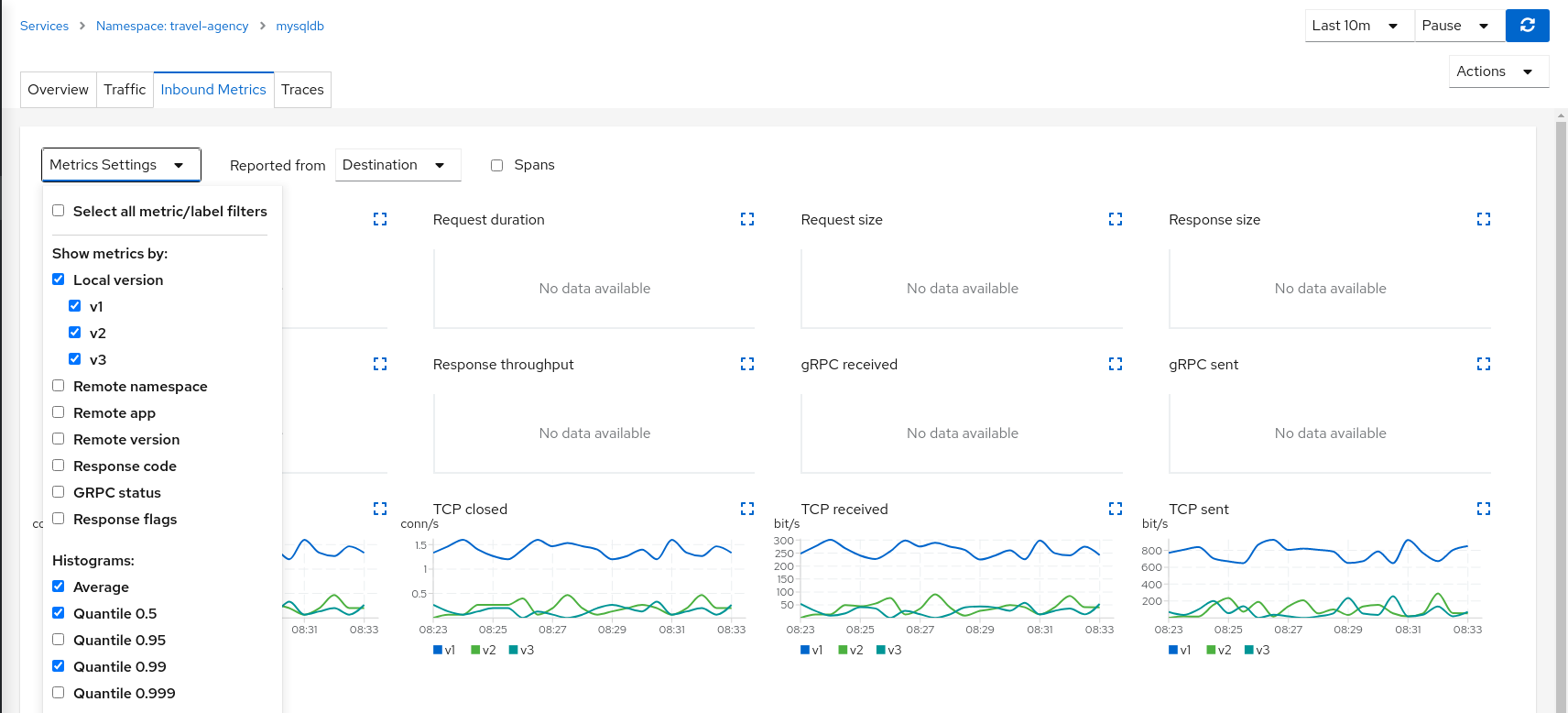
The charts show more peaks in mysqldb-v2 compared to mysqldb-v3 but overall a similar behavior, so it’s probably safe to choose either strategy to shift all traffic.
Step 5
Update or delete Istio ConfigurationAs part of this step you can update the TCP Traffic Shifting scenario to test a different distribution. When finished, you can delete the generated Istio config for the mysqldb service.
Request Timeouts
In the Fault Injection step we showed how we could introduce a delay in the critical hotels service and test the resilience of the application.
The delay was propagated across services and Kiali showed how services accepted the delay without creating errors on the system.
But in real scenarios delays may have important consequences. Services may prefer to fail sooner, and recover, rather than propagating a delay across services.
This step will show how to add a request timeout for one of the portals deployed in travel-portal namespace. The travels.uk and viaggi.it portals will accept delays but voyages.fr will timeout and fail.
Step 1
Use the Fault Injection Wizard on hotels service to inject a delayRepeat the Fault Injection step to add delay on hotels service.
Step 2
Use the Request Routing Wizard on travels service to add a route rule with delay for voyages.frAdd a request timeout only on requests coming from the voyages.fr portal. This requires two route rules:
Use the Request Matching tab to add a matching condition for the portal header with voyages.fr value.

Use the Request Timeouts tab to add an HTTP Timeout with default values.
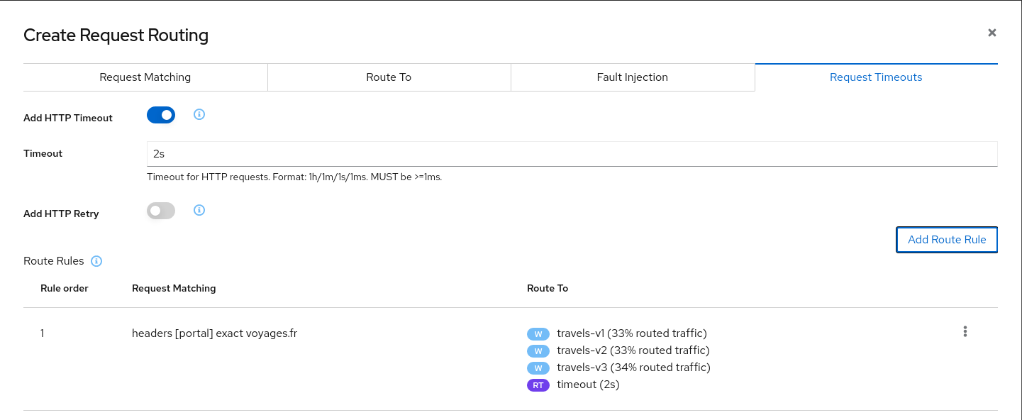
Add the first route rule to the scenario.
Add a second rule to match any request.
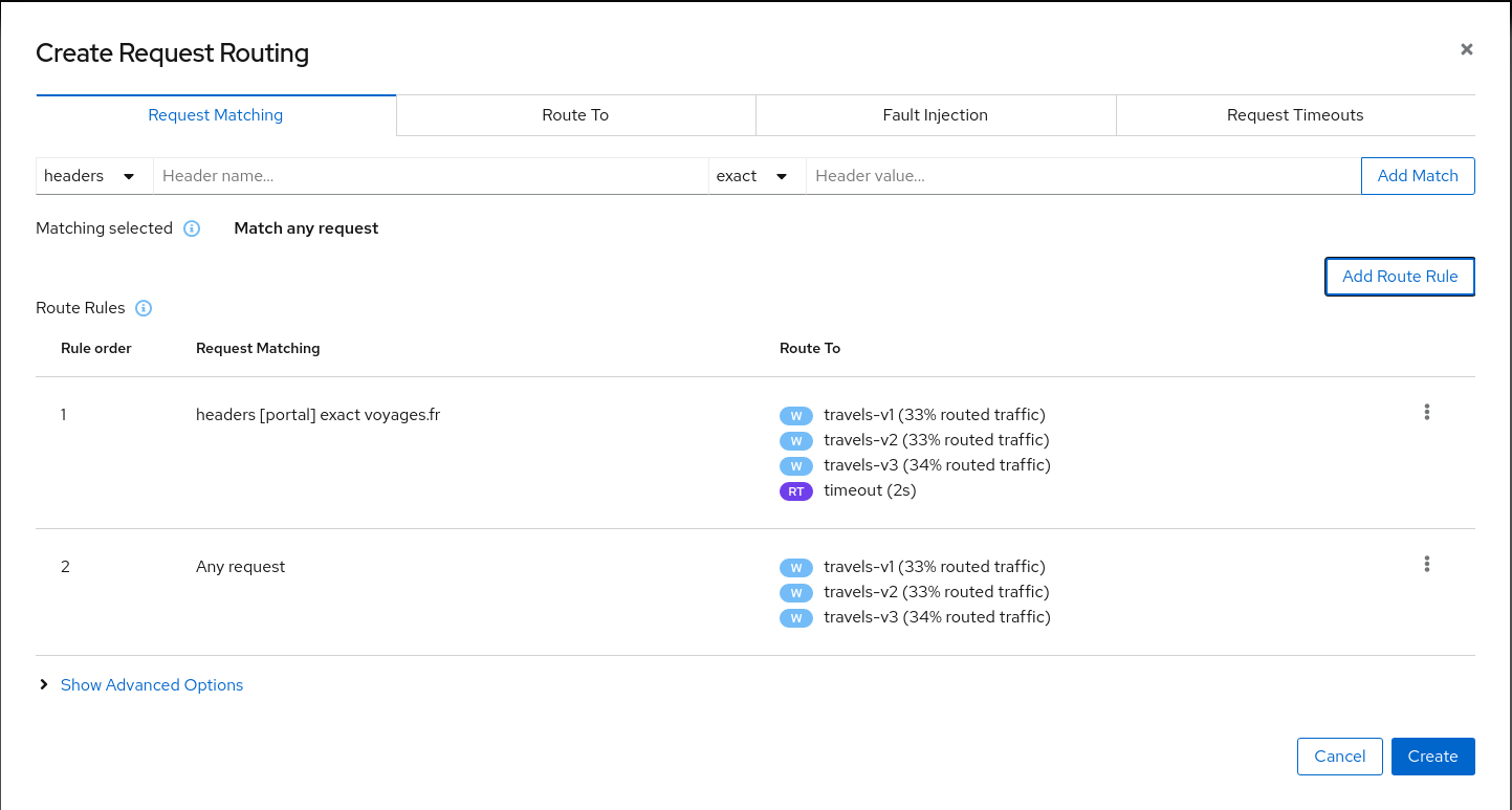
Create the request routing scenario. With this configuration, requests coming from voyages.fr will match the first rule and all others will match the second rule.
Step 3
Review the impact of the request timeout in the travels serviceCreate the rule. The Graph will show how requests coming from voyages.fr start to fail, due to the request timeout introduced.
Requests coming from other portals work without failures but are degraded by the hotels delay.
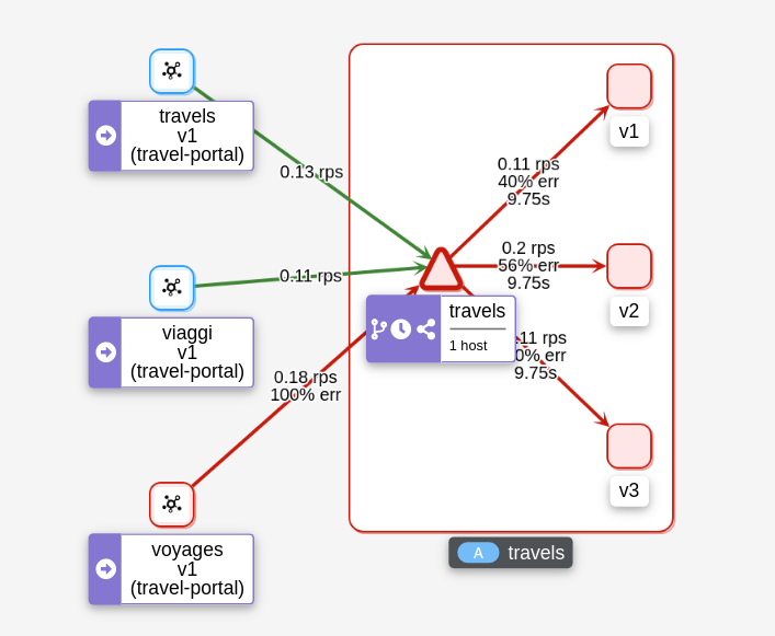
This scenario can be visualized in detail if we examine the “Inbound Metrics” and we group by “Remote app” and “Response code”.
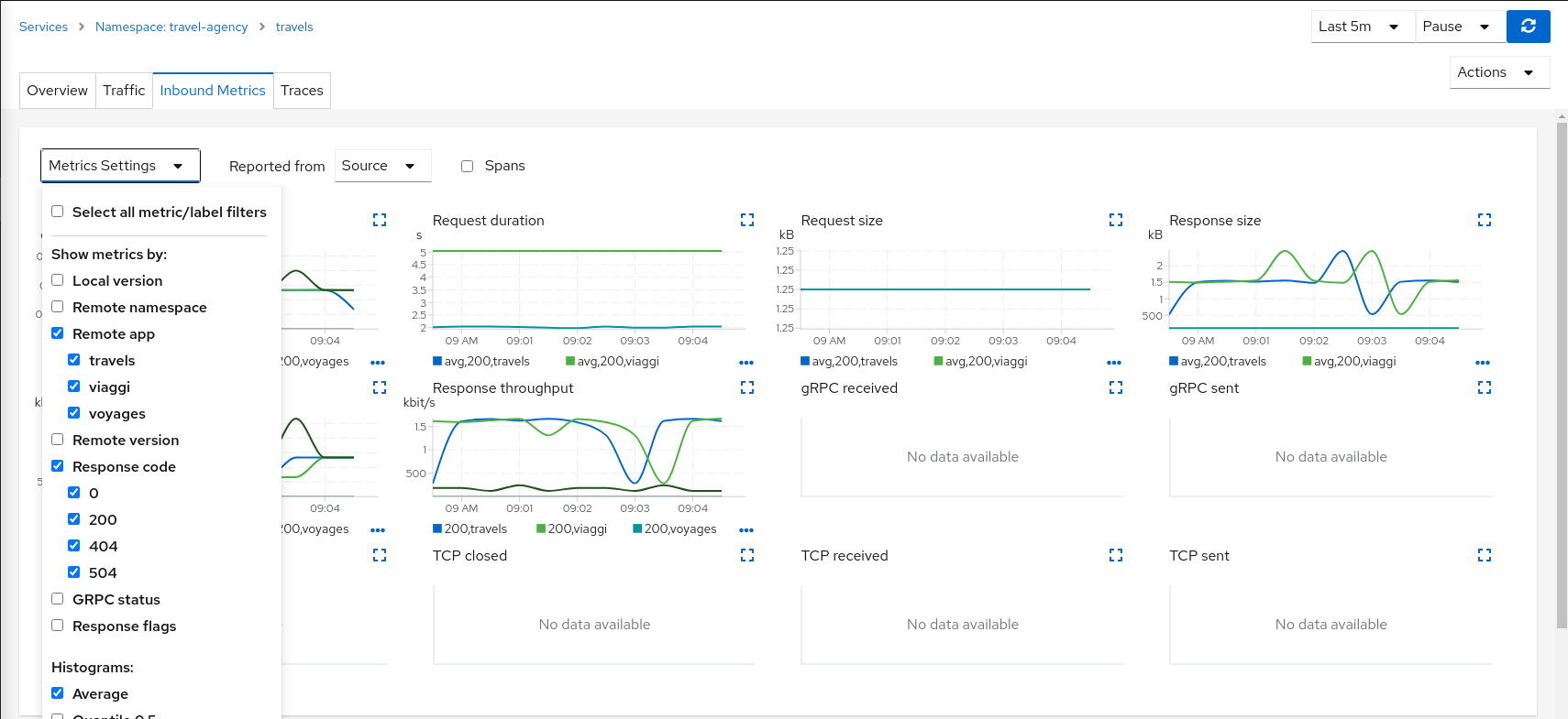
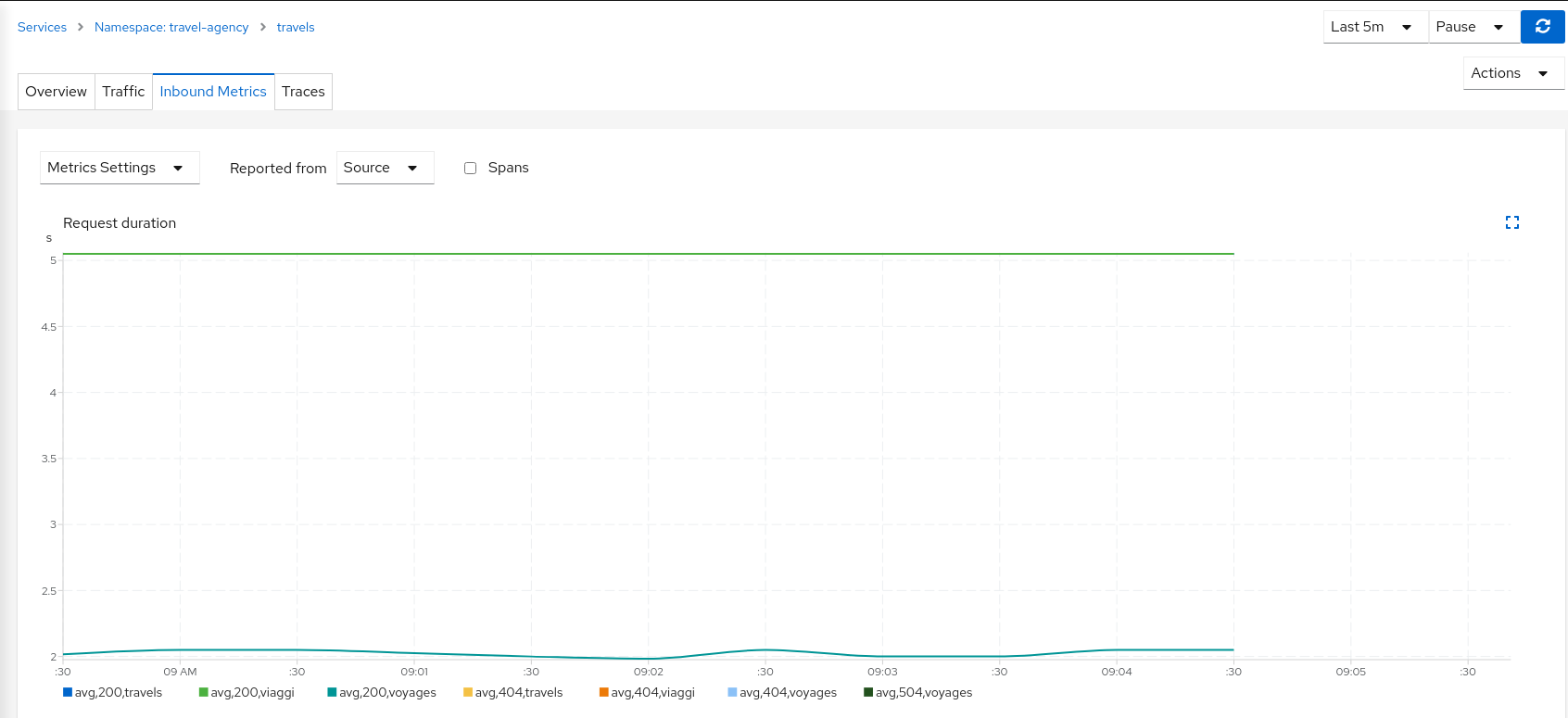
As expected, the requests coming from voyages.fr don’t propagate the delay and they fail in the 2 seconds range, while requests from other portals don’t fail but they propagate the delay introduced in the hotels service.
Step 4
Update or delete Istio ConfigurationAs part of this step you can update the scenarios defined around hotels and travels services to experiment with more conditions, or you can delete the generated Istio config in both services.
Circuit Breaking
Distributed systems will benefit from failing quickly and applying back pressure, as opposed to propagating delays and errors through the system.
Circuit breaking is an important technique used to limit the impact of failures, latency spikes, and other types of network problems.
This step will show how to apply a Circuit Breaker into the travels service in order to limit the number of concurrent requests and connections.
Step 1
Deploy a new loadtester portal in the travel-portal namespaceIn this example we are going to deploy a new workload that will simulate an important increase in the load of the system.
OpenShift
OpenShift users may also need to add the associated loadtester ServiceAccount to the necessary SecurityContextConstraints.kubectl apply -f <(curl -L https://raw.githubusercontent.com/kiali/demos/master/travels/travel_loadtester.yaml) -n travel-portal
The loadtester workload will try to create 50 concurrent connections to the travels service, adding considerable pressure to the travel-agency namespace.
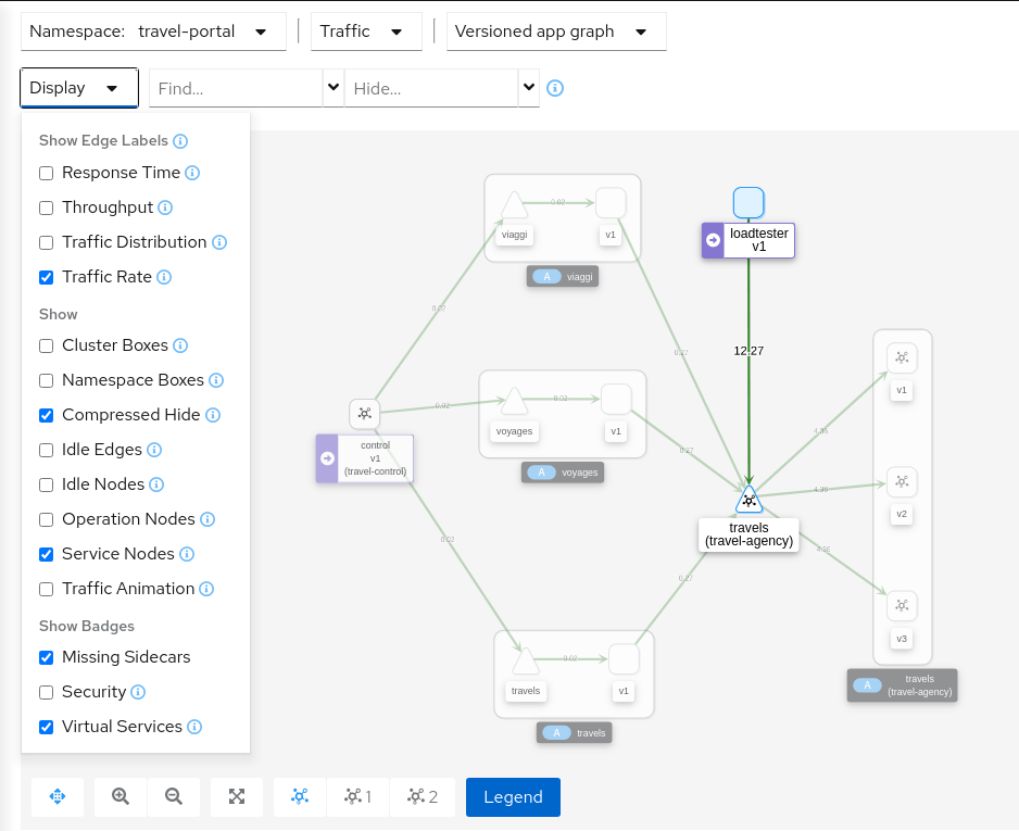
The Travel Demo application is capable of handling this load and at first glance it doesn’t show unhealthy status.
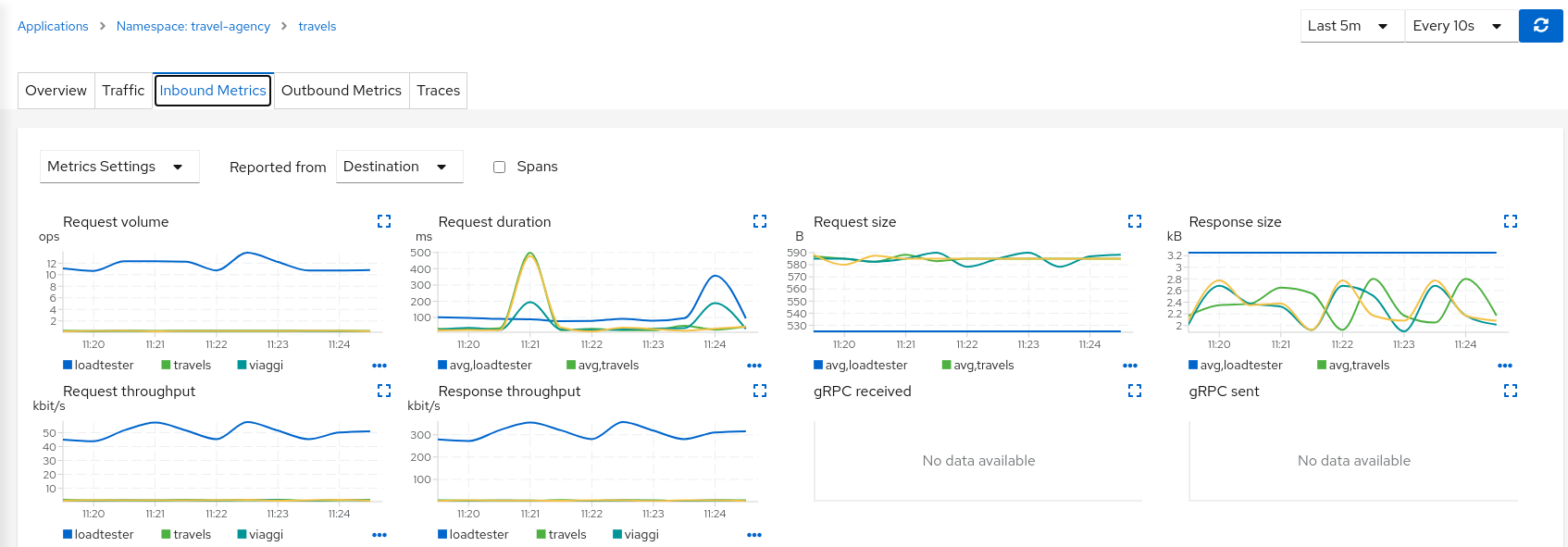
But in a real scenario an unexpected increase in the load of a service like this may have a significant impact on the overall system status.
Step 2
Use the Traffic Shifting Wizard on travels service to generate a traffic rule- Open travels service detail in the travel-agency namespace.
- Select Actions → Request Routing.
- Click Add Rule to distribute traffic (evenly) to the travels workloads.
- Click Advanced Options → Circuit Breaker tab.
- Enable Add Connection Pool and Add Outlier Detection with the default settings.
- Create the Circuit Breaker.
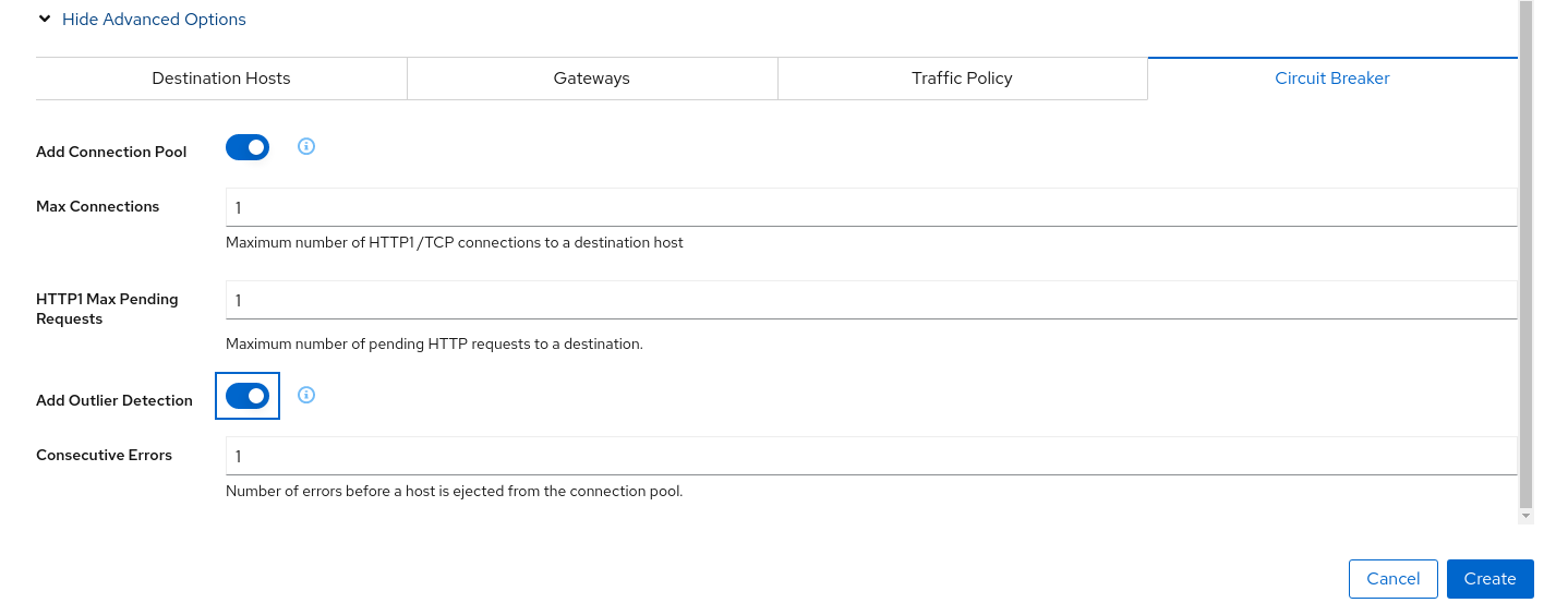
The “Connection Pool” settings will indicate that the proxy sidecar will reject requests when the number of concurrent connections and requests exceeds more than one.
The “Outlier Detection” will eject a host from the connection pool if there is more than one consecutive error.
Step 3
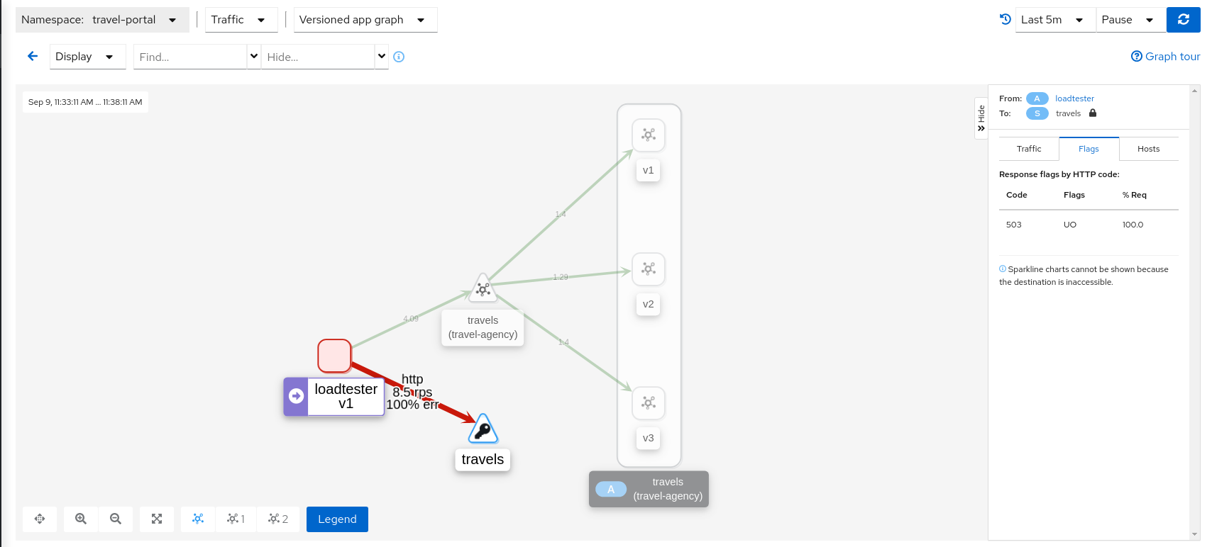
Study the behavior of the Circuit Breaker in the travels serviceIn the loadtester versioned-app Graph we can see that the travels service’s Circuit Breaker accepts some, but fails most, connections.
Remember that these connections are stopped by the proxy on the loadtester side. That “fail sooner” pattern prevents overloading the network.
Using the Graph we can select the failed edge, check the Flags tab, and see that those requests are closed by the Circuit breaker.
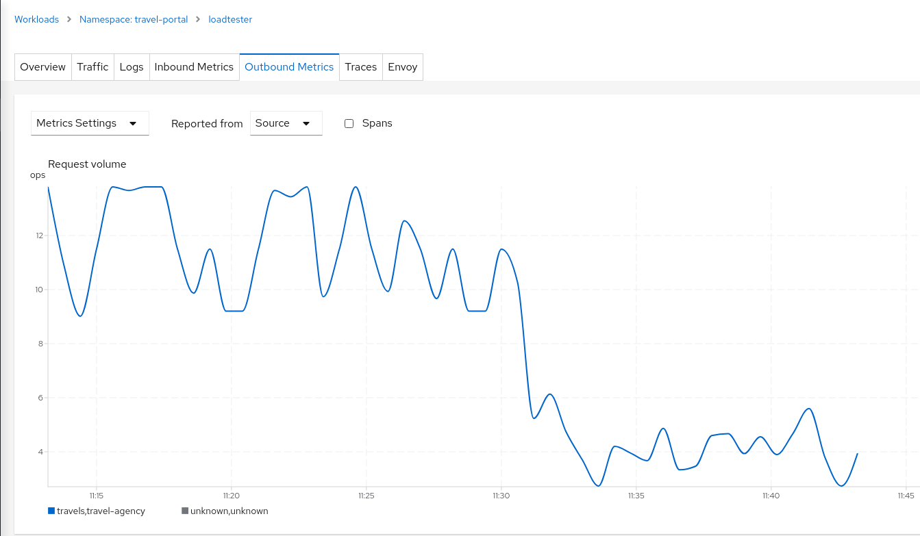
If we examine the “Request volume” metric from the “Outbound Metrics” tab we can see the evolution of the requests, and how the introduction of the Circuit Breaker made the proxy reduce the request volume.
Step 4
Update or delete Istio ConfigurationAs part of this step you can update the scenarios defined around the travels service to experiment with more Circuit Breaker settings, or you can delete the generated Istio config in the service.
Understanding what happened:
(iii) Connection Pool Settings
(iv) Envoy’s Circuit Breaking Architecture
Mirroring
This tutorial has shown several scenarios where Istio can route traffic to different versions in order to compare versions and evaluate which one works best.
The Traffic Shifting step was focused on the travels service adding new travels-v2 and travels-v3 workloads and the TCP Traffic Shifting showed how this scenario can be used on TCP services like the mysqldb service.
Mirroring (or shadowing) is a particular case of the Traffic Shifting scenario where the proxy sends a copy of live traffic to a mirrored service.
The mirrored traffic happens out of band of the primary request path. It allows for testing of alternate services, in production environments, with minimal risk.
Istio mirrored traffic is only supported for HTTP/gRPC protocols.
This step will show how to apply mirrored traffic into the travels service.
Step 1
Use the Traffic Shifting Wizard on travels serviceWe will simulate the following:
- travels-v1 is the original traffic and it will keep 80% of the traffic
- travels-v2 is the new version to deploy, it’s being evaluated and it will get 20% of the traffic to compare against travels-v1
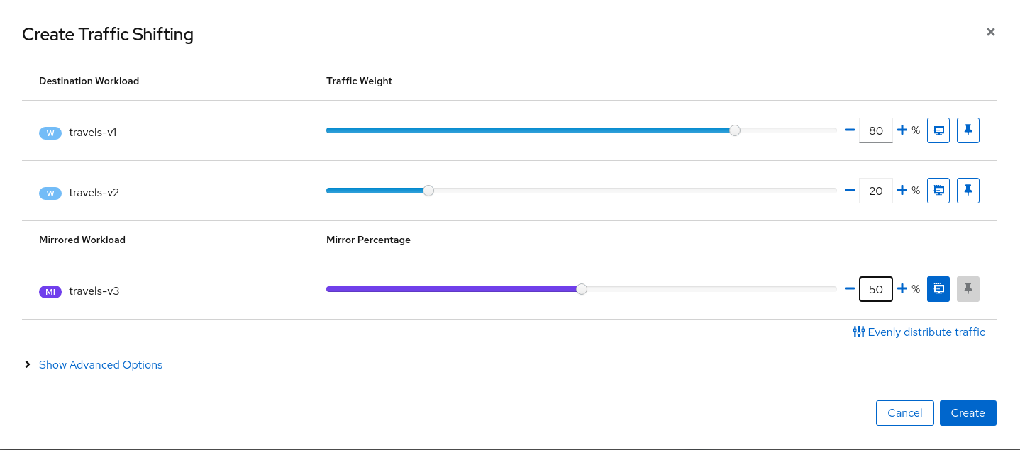
- But travels-v3 will be considered as a new, experimental version for testing outside of the regular request path. It will be defined as a mirrored workload on 50% of the original requests.
- Open travels service detail in the travel-agency namespace.
- Select Actions → Traffic Shifting.
- Set the 80%/20% loads for travels-v1 and travels-v2.
- Click the Mirroring icon for travels-v3.
- Set the 50% mirroring load.
- Create the Traffic Shifting with Mirroring.
Step 2
Examine Traffic Shifting distribution from the travel-agency GraphNote that Istio does not report mirrored traffic telemetry from the source proxy. It is reported from the destination proxy, although it is not flagged as mirrored, and therefore an edge from travels to the travels-v3 workload will appear in the graph. Note the traffic rates reflect the expected ratio of 80/20 between travels-v1 and travels-v2, with travels-v3 at about half of that total.
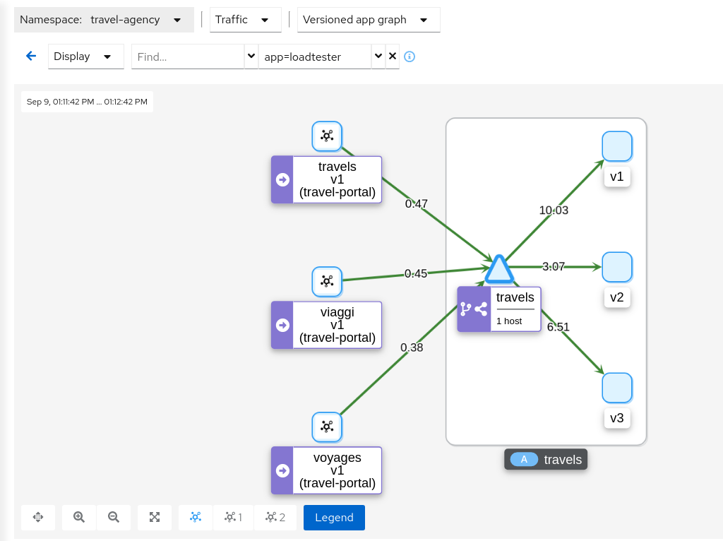
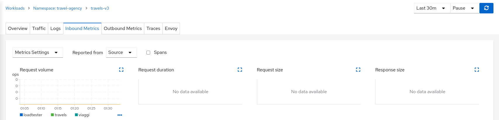
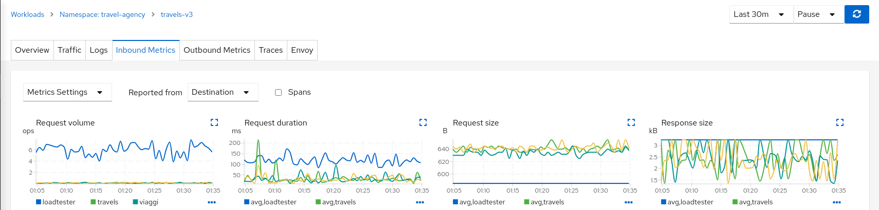
This can be examined better using the “Source” and “Destination” metrics from the “Inbound Metrics” tab.
The “Source” proxy, in this case the proxies injected into the workloads of travel-portal namespace, won’t report telemetry for travels-v3 mirrored workload.
But the “Destination” proxy, in this case the proxy injected in the travels-v3 workload, will collect the telemetry from the mirrored traffic.
Step 3
Update or delete Istio ConfigurationAs part of this step you can update the Mirroring scenario to test different mirrored distributions.
When finished you can delete the generated Istio config for the travels service.